

This article provides a comprehensive overview of all the cables required to connect your PC components to the power supply to ensure their stable operation. It also includes expert recommendations for proper installation to maximize the longevity of both your PSU and your system.
How to connect the cables to the PC power supply unit?
Connecting cables to your PSU is an important step in building a well-running system. Do it carefully and only after you have learnt enough information about the entire process beforehand. The way you connect cables affects how well your PSU works, how efficiently it runs, and also creates safety during operation.
To get cable installation right the first time, follow these steps we have outlined in the following PSU cables guide:
1. Make sure that the computer is turned off and disconnected from the mains (the PSU switch is in the OFF position and the AC power cord unplugged from the wall socket).
2. Insert the PSU into the appropriate space in the case. Usually, the power supply is installed at the bottom of the case, but it is better to check your PC case manual just to make sure that the fan is facing the ventilation opening. Correct PSU placement ensures proper airflow inside the case. Secure the PSU to the back of the case using the screws provided inside the packaging.
3. Connect the cables to the motherboard in two steps.
- First, connect the motherboard which is the ATX 24-pin main power cable. It is usually connected to the right of the RAM slots.
- Second, connect the CPU (4-pin or 8-pin (4+4)). It usually connects next to the processor socket, in the upper left corner of the motherboard.
4. The next step is to connect the GPU. Use the right number of cables marked “PCIe” (usually 6+2-pin connectors), required according to the video card model. You can refer to our guide about this.
5. Finally, connect the power cables for storage devices and peripherals by using SATA cables for the SSDs and thin cables with an L-shaped connector for the hard drives. Also, connect the cables for the fans or RGB controllers; use either Molex or SATA cables based on your device’s requirements.
Keep in mind a few recommendations for safe and efficient PSU operation. Use only the cables that came with your PSU, as others may not fit the connectors or may not be calibrated for the PSU that they are being used with. We recommend connecting the cables to your components first and only then securing the PSU in the case, as this makes it easier to manage the wiring.
What types of connectors and cables are used in PC power supplies?
The following power supply connector types are used in modern PCs:
24-pin ATX (20+4)
The main cable that supplies power to the motherboard. Modern versions are 24-pin, but the cable is often split into 20+4 pins for compatibility with older motherboards. It makes sense in case you have an older motherboard and a newer power supply.
CPU / EPS (4-pin, 4+4-pin, or 8-pin)
It supplies power to the processor. It usually comes in a 4+4 pin version, which you can connect as two 4-pin connectors (if the board supports it).
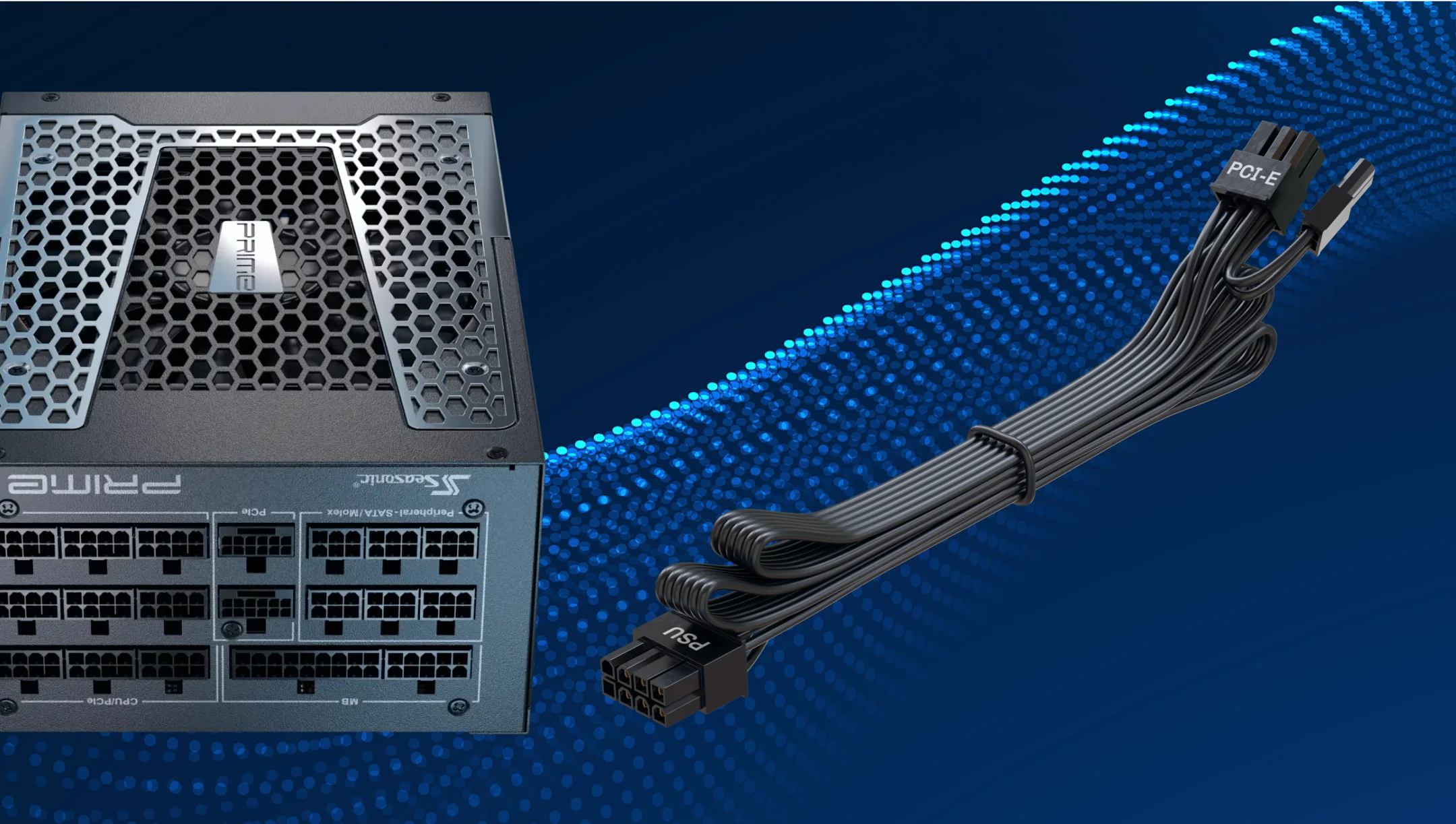
PCIe power connector (6-pin, 6+2-pin, 12VHPWR / 12V-2×6)
It is used to power video cards. Standard cables are 6- and 6+2-pin. New cards support 16-pin 12VHPWR or the newest 12V-2×6 version.
SATA Power (15-pin)
For powering storage devices (SSD, HDD), optical drives, and peripherals. The connector is flat, with an L-shaped profile for proper connection.
Molex (4-pin)
A traditional connector for older hardware types, such as HDD, fans, and optical drives. It is used less frequently, but may still be needed for peripheral devices or adapters.
To avoid incorrect connections, each cable connector has its own special shape (keying). For more information about cables, you can refer to our FAQ.
What is a 24-pin ATX connector, and where does it plug in?
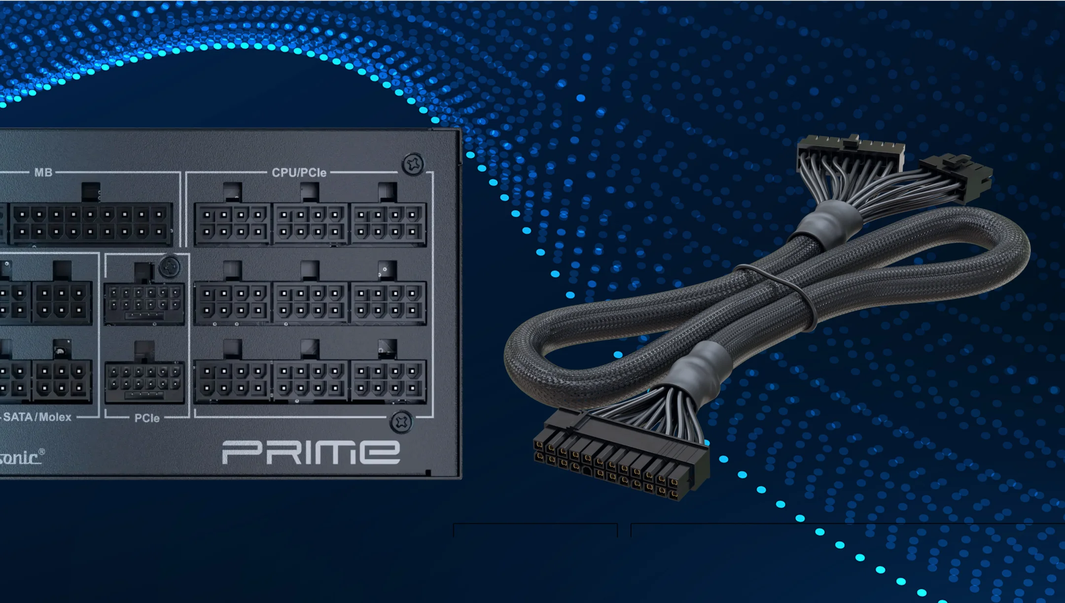
The 24-pin ATX connector is the primary power delivery interface between the PSU and the motherboard. It uses Molex Mini-Fit Jr. contacts and its specifications are defined by the ATX12V v2.x standard. Through this connector, the PSU supplies a mix of voltages and control signals that are essential for system operation.
The connector provides the motherboard with +3.3 V, +5 V, +12 V, and +5VSB (standby power) rails, as well as critical control signals such as PS_ON# (to switch the PSU on/off), PWR_OK (power-good signal), and ground lines. These signals allow the motherboard to properly sequence startup and shutdown, and they ensure stable operation.
Previously, ATX motherboards used a 20-pin connector, but with the growing power requirements of CPUs, GPUs, and peripherals, the specification was expanded to 24 pins (adding one +3.3 V, one +5 V, one +12 V, and an additional ground). This increased current capacity helped to maintain stable power delivery for more demanding components.
On most motherboards, the 24-pin connector is located near the edge of the board, next to the memory (DIMM) slots. The connector is keyed with uniquely shaped cutouts to prevent incorrect insertion, and most PSUs today use a 20+4-pin split design, which maintains backward compatibility with older 20-pin motherboards.
Where does the 4-pin ATX12V connector go?
The 4-pin ATX12V connector is a CPU power cable designed to supply +12V power directly to the processor’s voltage regulator on the motherboard. This connector plugs into the 4-pin ATX12V (CPU power) socket, typically located near the CPU socket. On motherboards, it may be labeled as CPU_PWR, ATX12V, P4, or simply 12V.
In case your motherboard has a 4-pin CPU power connector, you can still use the 4+4-pin CPU cable. Simply separate the two parts and use only one 4-pin connector to plug into the motherboard. Leave the other 4-pin half unused. The PSU side of the cable remains connected as normal to the CPU/PCIe port on the power supply. This is completely safe and does not affect the functionality of your motherboard.
Before installing, check the cable’s orientation carefully to avoid damaging the contacts.
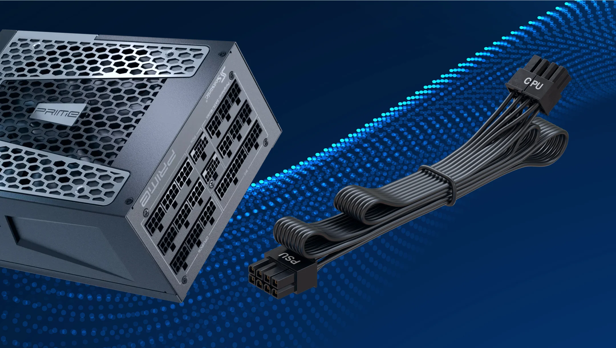
How does the 8-pin EPS12V connector power the CPU, and where is it located?
The 8-pin EPS12V connector supplies +12V power directly to the CPU’s voltage regulation circuitry on the motherboard. Its purpose is to provide a stable and sufficient current to the processor, ensuring reliable operation even under heavy loads such as gaming, streaming, or overclocking.
This connector plugs into the 8-pin CPU power socket on the motherboard, usually located next to the processor socket. It may be labeled as CPU_PWR, EPS12V, or simply 12V.
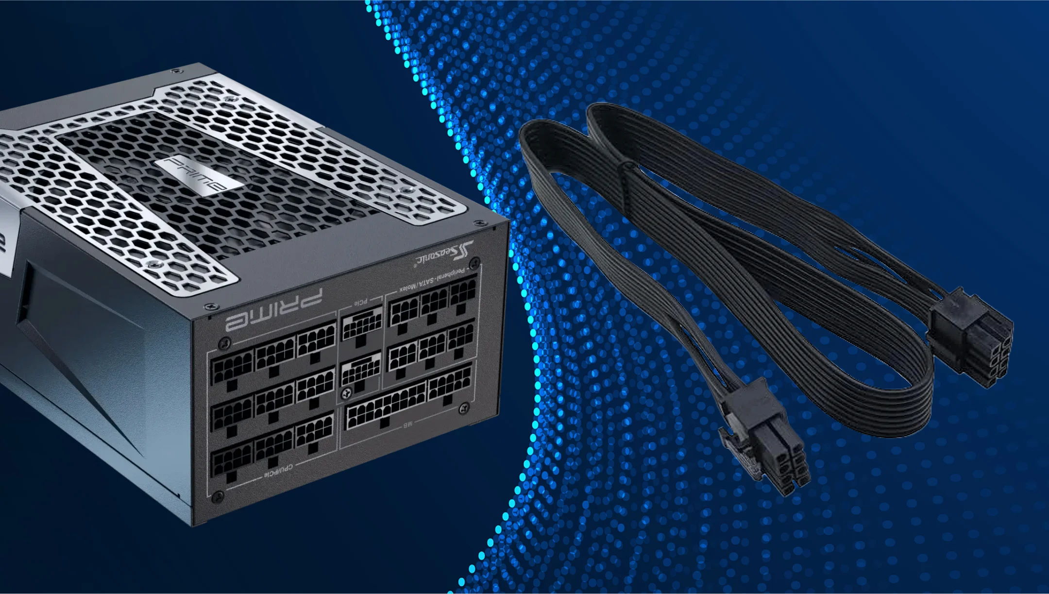
What is the PCIe power connector?
A PCIe power connector is a cable that delivers additional power from the PSU to PC components, most commonly graphics cards (GPUs), to ensure stable operation under higher power loads. The motherboard’s PCIe slot itself only provides up to 75 W, so more powerful GPUs require dedicated PSU connectors.
Here are the key PCIe power connectors:
- 6-pin PCIe
Provides up to 75 W of additional power. Commonly used for entry-level or older graphics cards. Connects to a 6-pin socket on the GPU. - 8-pin PCIe
Provides up to 150 W of power. Standard for mid-range and many high-end graphics cards. Connects to an 8-pin socket on the GPU. - 6+2-pin PCIe
A flexible connector that can function as either a 6-pin or an 8-pin connector. Connected to the GPU’s corresponding socket, it provides up to 150 W of power, depending on the configuration. - 12VHPWR (12 V High Power)
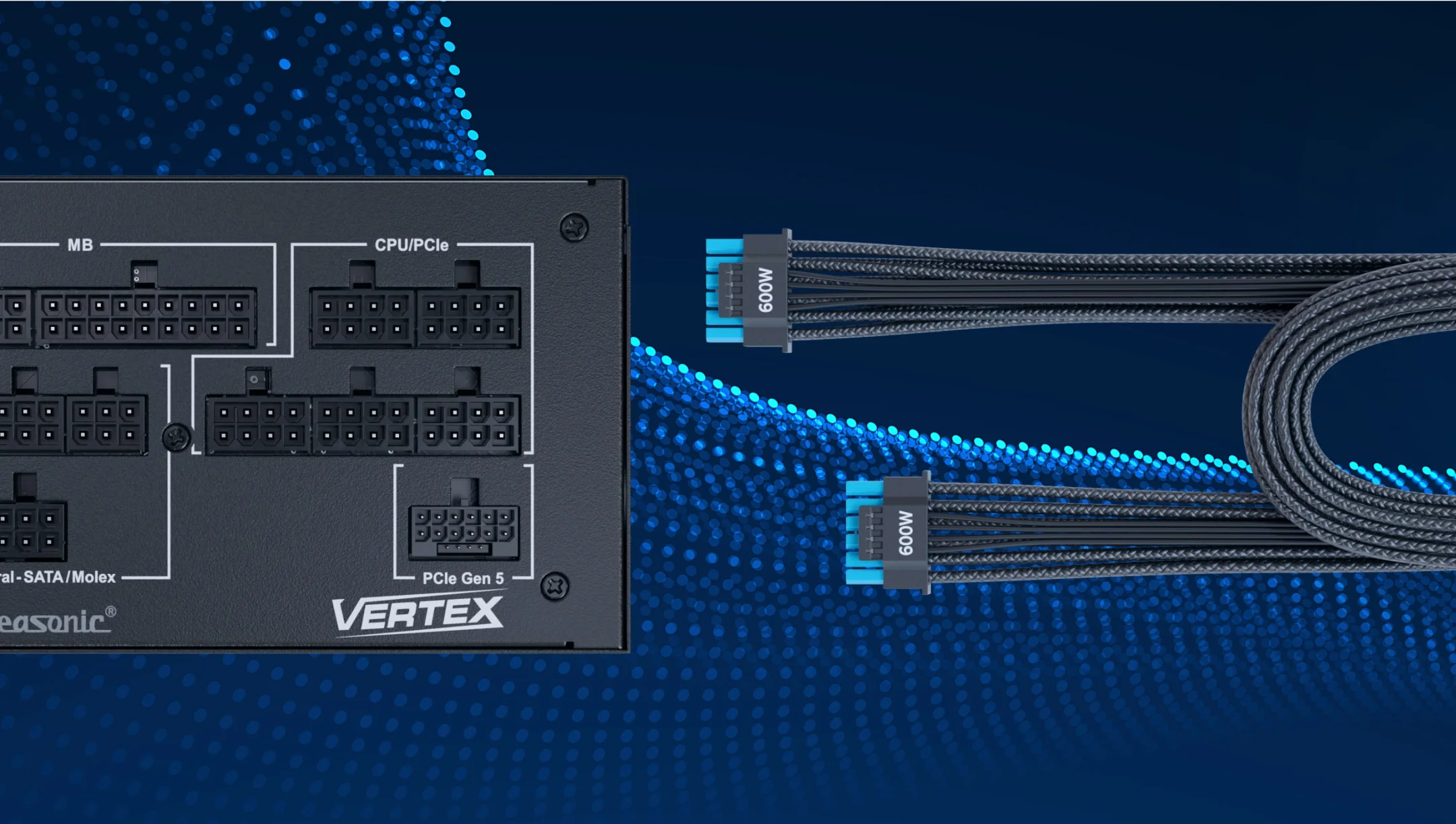
The new PCIe Gen 5.0 connector, capable of delivering up to 600 W through a single cable. It is used by the latest high-performance GPUs and plugs into the 12+4-pin connector.
Which components require it?
PCIe power connectors are most needed for the two vital PC components, the GPU and the motherboard, with additional PCIe connectors. Here are some additional details on this.
GPU
GPUs can be powered by 6-pin, 8-pin, or the latest 12VHPWR cables. Modern graphics cards, especially high-performance models, require additional power via a PCIe connector that provides the power needed to run heavy loads, like gaming, streaming, or 3D rendering. Additionally, some high-end GPUs need two or even three 8-pin PCIe cables to run at full power.
Motherboards
Certain motherboards have additional PCIe connectors that are required to power certain components. This is crucial, especially when using multiple GPUs or high-performance accessories.
What is the 12V-2×6 connector?
The 12V-2×6 connector is the updated power standard for modern GPUs, introduced alongside the ATX 3.1 and PCIe 5.1 specifications. It is the successor to the earlier 12VHPWR connector and was designed to improve safety and reliability in high-power graphics card applications.
- Single 12-pin main connector + 4 sense pins (often referred to as a 16-pin connector).
- Supports up to 600 W of continuous power delivery, suitable for high-performance GPUs.
- Fully compliant with ATX 3.1 and PCIe 5.1 standards.
The 12V-2×6 connector features an improved pin design compared to the older 12VHPWR connector. The sense pins are shorter (1.5 mm) so that they only engage once the connector is fully seated, preventing misreadings or unsafe startups. At the same time, the power terminals are slightly longer (+0.25 mm), which ensures a more reliable electrical contact. Together, these changes greatly reduce the risks of poor seating, arcing, and overheating.
Why is it important for modern GPUs?
High-end GPUs often exceed the average of 400 W to 500 W of power draw. Since 6-pin (75 W) and 8-pin (150 W) connectors are limited in power delivery, manufacturers had to use multiple 8-pin connectors, but adding more was not practical.
The 12V-2×6 connector solves this problem by delivering up to 600 W through a single, safer connector, meeting modern GPUs’ power needs without the drawbacks of older designs.
In simple terms:
- The 12V-2×6 connector provides enough power for powerful GPUs, even under high loads during games or rendering.
- It provides safe and stable power, reducing the risk of overheating contacts and damaging the video card.
- The new standard is compatible with ATX 3.1 and PCIe 5.1 standards, making it modern and reliable for modern GPUs.
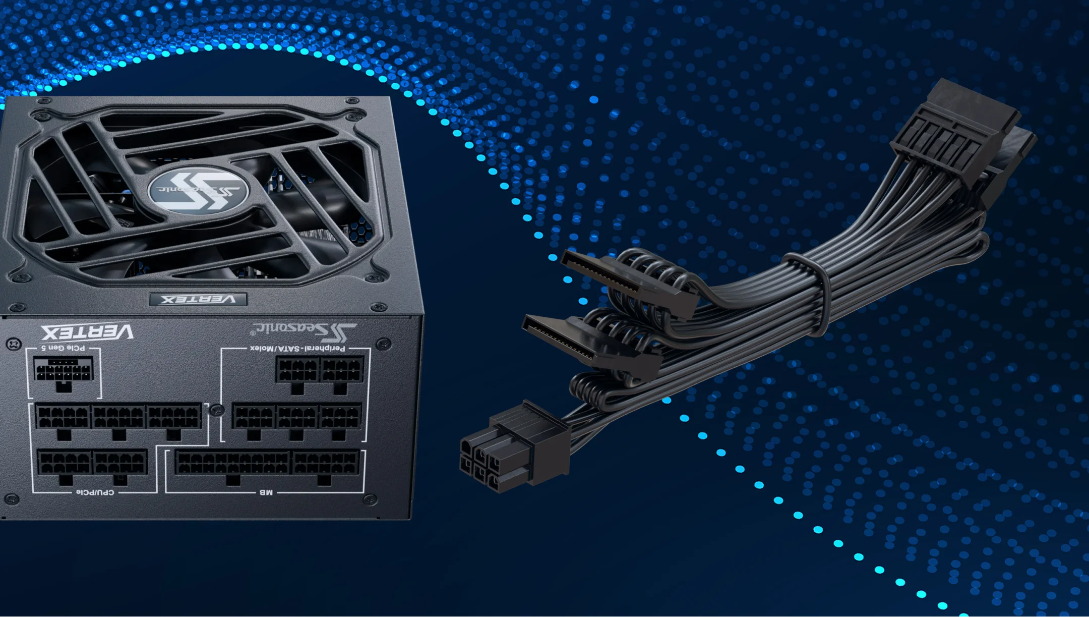
Where do you connect SATA power cables?
SATA power cables are used to supply electricity to storage devices such as HDDs, SSDs, and optical drives that rely on the SATA interface. These flat cables feature a 15-pin SATA power connector that typically comes included with the power supply unit (PSU).
Unlike SATA data cables, which connect the drive to the motherboard, SATA power cables link directly from the PSU to the device. A single cable often includes multiple connectors, making it possible to power several drives with one cable.
On modular PSUs, SATA power cables plug into the dedicated SATA output on the PSU side (usually a 6-pin connector). On non-modular PSUs, the SATA power cables are permanently attached to the unit and ready to use.
What is the 4-pin Molex connector?
The 4-pin Molex connector is one of the older power connectors found in PCs. It provides two voltages to devices: +12 V (yellow wire), +5 V (red wire), and two ground wires (black).
Historically, Molex connectors were widely used to power PATA (IDE) hard drives, optical drives, case fans, and some graphics cards. Although they are less common in modern systems, many power supplies still include Molex cables to ensure compatibility with legacy components.

Differences between similar PSU connectors
Since power supplies and PC components have different power requirements and are frequently updated, their connectors may also change. This is also why new types of connectors keep appearing. Let us dive into their differences in detail.
SATA vs. Molex
| SATA | Molex |
|---|---|
| Used to power modern storage devices – SSD, HDD, CD/DVD drives. | An older standard that is still popular for peripherals. For example, older HDDs, fans, and RGB controllers. It is more reliable in transmitting high power, but bulky and less convenient in cable management. |
6-pin PCIe vs. 6+2-pin (8-pin PCIe)
| 6-pin PCIe | 6+2-pin (8-pin PCIe) |
|---|---|
| Delivers up to 75 W, roughly equivalent to a mid-range GPU. | Operates as either a 6-pin or 8-pin connector and delivers up to 150 W for more powerful GPUs. |
4-pin EPS vs. 8-pin EPS (for CPU)
| 4-pin EPS | 8-pin EPS (often 4+4) |
|---|---|
| Old CPU power supply option, suitable for simple processors with moderate power consumption. | Modern standard for powerful CPUs that provides a more stable and greater power supply. Required for overclocking and other high-load tasks. |
How to properly manage and safely route PSU cables?
First, always start with planning. Before connecting the components, decide which cables will be needed and which ones can be connected later. If you have a fully-modular or semi-modular PSU, connect only the cables that are necessary. This will help you avoid clutter inside the case and piling up dust on PC components.
Run cables behind the motherboard’s rear panel through special holes in the case (rubber or metal grommets). This helps keep them away from fans and heat-generating components to improve air circulation.
Be careful not to bend or put unnecessary tension on the cables, as this can damage their insulation. Also, do not lay cables close to hot components, like CPU coolers or video cards. Excessive heat reduces the durability of the insulation over time, and there is a risk of rapid heat damage to your cables.
Conclusions
PSU cables play a key role in the stable and safe operation of a PC. They transmit power from the power supply unit to all PC components – the motherboard, CPU, GPU, storage devices, and peripherals. The right cable type and quality ensure safe and reliable connections and support for high-power components.
Properly organized cables also reduce electrical interference and support the stable operation of high-performance components. They make the system look neat and organized, especially if you have a case with a transparent side panel.